THIS CALCULATION PAGE IS DESIGNED FOR A DESKTOP DEVICE
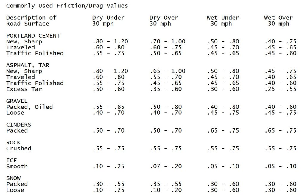
The following friction data was taken from “Friction Applications in Accident Reconstruction” by Warner et al. (Society of Automotive Engineers document number: SAE 830612). It has been provided without any warranty as to suitability, accuracy, or usefulness to the user. IBFSA (Pty) Ltd does not endorse this data in any form or its usage and provides it solely as a convenience to the user:-
Surface Selection:
| Surface Type: | ||
| Drag Factor Range: | to | Enter or select drag factor range (G) |
Distance:
| d (distance): | meters | Skid distance in meters for visible tyre marks |
Formula:
Calculation 1 (Lowest Estimate)
ve = end velocity = 0.000 m/sec
a = accel/decel = -0.500 G = -4.905 m/sec²
d = distance = 30.000 meters
Calculation 2 (Highest Estimate)
ve = end velocity = 0.000 m/sec
a = accel/decel = -0.600 G = -5.886 m/sec²
d = distance = 30.000 meters
Final Results
Final Result (Velocity Range) = 17.20 to 18.80 m/sec
Final Result (Speed Range) = 61.92 to 67.68 km/h
The following friction data was taken from “Friction Applications in Accident Reconstruction” by Warner et al. (Society of Automotive Engineers document number: SAE 830612). It has been provided without any warranty as to suitability, accuracy, or usefulness to the user. IBFSA (Pty) Ltd does not endorse this data in any form or its usage and provides it solely as a convenience to the user:-
Surface Selection:
| Surface Type: | ||
| μ (friction) range: | to | Coefficient of friction (G) |
Geometry & Grade:
| r (radius of curve): | meters | Path radius in meters |
| G (grade in direction of slip): | decimal | Eg: +0.05 for 5% downhill, -0.05 for 5% uphill |
Formula:
Calculation 1 (Using μmin)
g = gravitational constant = 9.810 m/sec²
r = 180.000 meters
μ = 0.800
G = 0.000 decimal
Calculation 2 (Using μmax)
g = gravitational constant = 9.810 m/sec²
r = 180.000 meters
μ = 1.200
G = 0.000 decimal
Final Results
Critical Speed Range (v): 37.585 to 46.027 m/sec
Critical Speed Range: 135.306 to 165.698 km/h
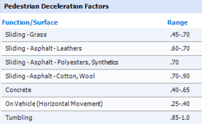
The following friction data was taken from “Friction Applications in Accident Reconstruction” by Warner et al. (Society of Automotive Engineers document number: SAE 830612) and/or from Friction Data contained in CrashMath Software by Visual Systems. It has been provided without any warranty as to suitability, accuracy, or usefulness to the user. IBFSA (Pty) Ltd does not endorse this data in any form or its usage and provides it solely as a convenience to the user:-
Deceleration Factor (μ) Selection:
| Clothing/Surface: | ||
| μ (single value): | (G) | Choose a preset or enter μ directly. Both formulas use this same μ. |
Inputs:
| dt (throw distance): | meters | Distance from impact to pedestrian rest |
| g (gravity): | g = 9.81 m/s² | Constant value used in calculations |
Formulas:
Calculation 1 – Minimum Speed (Vmin)
μ = 0.600 G
g = 9.810 m/sec2
d = distance thrown = 32.000 meters
Calculation 2 – Maximum Speed (Vmax)
μ = 0.700 G
g = 9.810 m/sec2
d = distance thrown = 32.000 meters
Final Results
Vmin = – m/sec = – km/h
Vmax = – m/sec = – km/h
The radius of a curve can be determined when the chord (C) and middle ordinate (Mo) are known, using the formula:
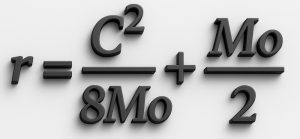
The chord is the straight-line distance between two points on the curved path, while the middle ordinate is the maximum perpendicular distance from the midpoint of the chord to the curved edge of the path.
These two measurements define the geometry of the curve and allow the radius to be calculated even if the full circle is not visible or accessible.
To ensure accuracy, both the chord and the middle ordinate should be measured carefully using two measuring devices, such as tape measures or laser distance tools, to confirm precision and minimize parallax error.
It is ideal to take these measurements along the curve path that would correspond to the center of mass of a vehicle, since this represents the true radius of motion during cornering.
When conditions or measurement opportunities vary, readings can also be taken along the inside and outside edges of the path, still referencing the center of mass path, to produce a range of possible radius values for more comprehensive analysis.
| C (chord): | meters | Straight-line distance between curve endpoints |
| Mo (middle ordinate): | meters | Perpendicular from chord midpoint to curve |
Formula:
Result
Radius r = 65.000 meters